Maintaining and Improving Irrigation Application Uniformity in Sprinkler and Drip Systems
Introduction
The goal of most irrigation system design and management is to provide all plants in an irrigated area with equal access to water. Ideally, each plant should receive the exact amount of water it needs. If a field needs 1 inch of water for irrigation, all parts of the field should receive exactly that. The reality is not so perfect. It is practically impossible to apply the same quantity of water to all plants in an irrigated area, plot, or field (we will use the term field to refer to any of these). In other words, all irrigation systems have some nonuniformities in the water delivered. Instead of designing and managing irrigation systems to apply water 100% uniformly, the goal of irrigation system designers, manufacturers, and operators should be to maximize irrigation uniformity within practical and economic constraints. In this fact sheet, we explain major causes of uneven water distribution in sprinkler and drip irrigation systems and suggest ways to improve or maintain uniformity.
Basic Pressurized Irrigation System Components
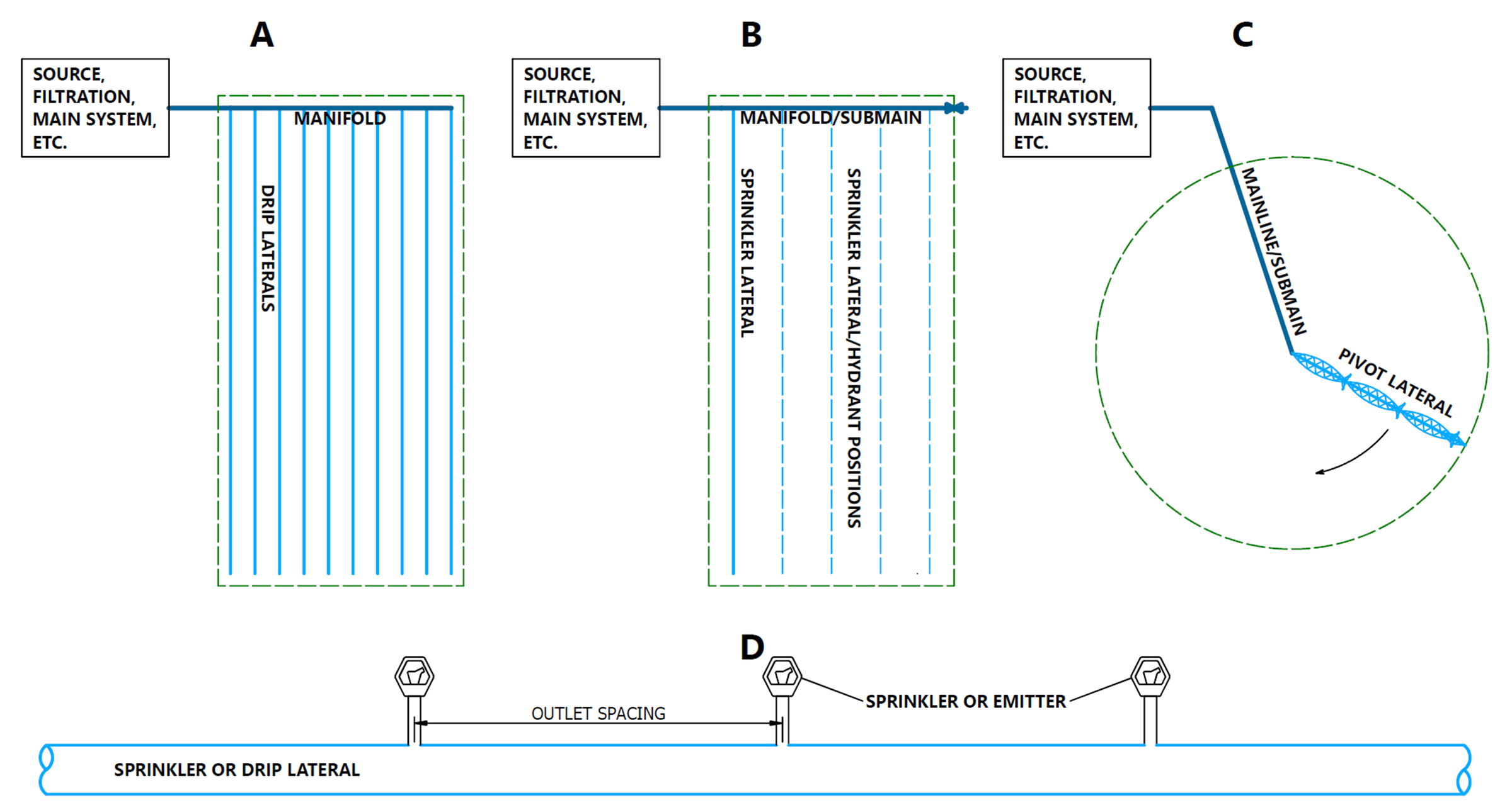
Factors affecting irrigation uniformity are often related to the design and function of irrigation systems themselves. For this reason, it is helpful first to consider the basic components of a pressurized irrigation system. In this fact sheet, a pressurized irrigation system can be represented as having a water source, which may include filtration and a main distribution system, a manifold or submain pipeline, one or more lateral pipelines, and outlets with sprinklers or drip emitters (Figure 1). Water flows from the main system/source into a manifold or submain pipeline. This submain feeds a series of lateral pipes, sometimes many at once and sometimes only a single pipeline at one time. In the case of periodic-move systems, like hand lines and wheel lines, the lateral pipe is moved periodically from one lateral position to another across the field. In the case of a center pivot or lateral-move system, a single lateral moves mechanically across or around the field. Lateral pipes have multiple outlets feeding drip emitters or sprinklers.
Nonuniformity Causes and Improvement Measures
Many factors affect irrigation uniformity. Eight causes of nonuniformity for sprinkler and drip irrigation systems are discussed below, along with recommended practices to maximize uniformity. These causes are:
- Pressure variation in the system.
- Manufacturing variation in nozzles, emitters, and other components.
- Insufficient sprinkler or emitter spacing.
- Irrigation system disrepair.
- Clogged nozzels or emitters.
- Weather conditions.
- Irrigation duration.
- Soil water infiltration variability
1. Pressure Variation in the System
Causes of Nonuniformity
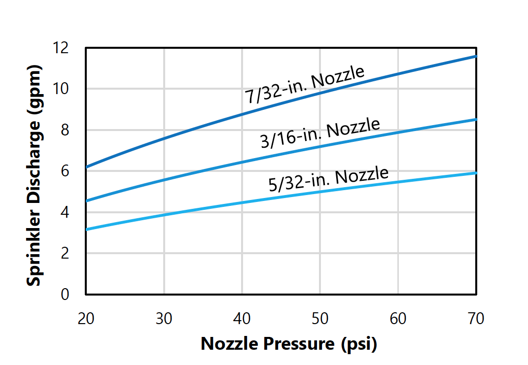
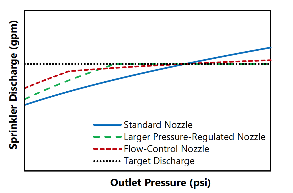
The water discharged by sprinklers and drip emitters depends on the supplied water pressure (see Figure 2). This pressure provides the force to push water through the sprinkler nozzle or the drip emitter. For a standard nozzle or emitter, as pressure increases, so does the discharge. So, if a lateral pipe has varying pressure along its length, then the nozzles/emitters along the pipe would then have different discharge rates. Pressure variation in an irrigation system is unavoidable, but proper design and operation can help minimize this variation.
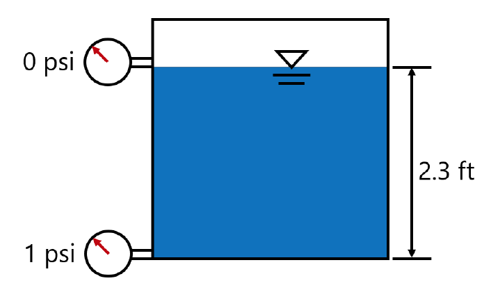
One cause of pressure variations in a piped irrigation system is differences in land elevation
throughout a field. A 2.3-foot change in elevation causes a 1 pound per square inch (psi) change in pressure. Going uphill drops pressure, going downhill increases pressure (Figure 3). So, if the land slope increases 2.3 feet from one side of a field to the other, water in a pipe would lose 1 psi of pressure over that distance due to elevation alone. Another cause of pressure variation in a pipe is water flow friction. This friction requires energy to overcome, and that energy comes from the pressure within the pipe. This causes reduced pressure between the upstream and downstream ends of a pipe caused by the water flow.
Evidence of Pressure Problems
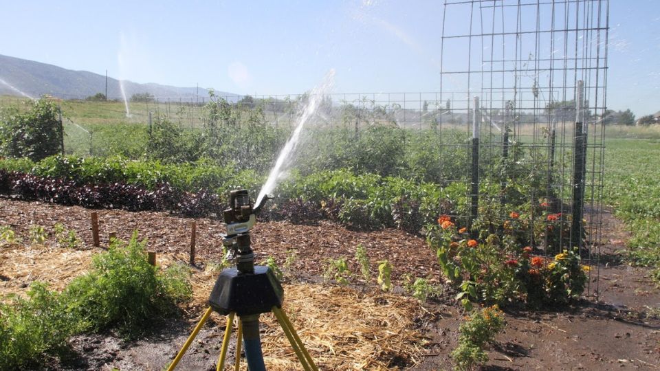
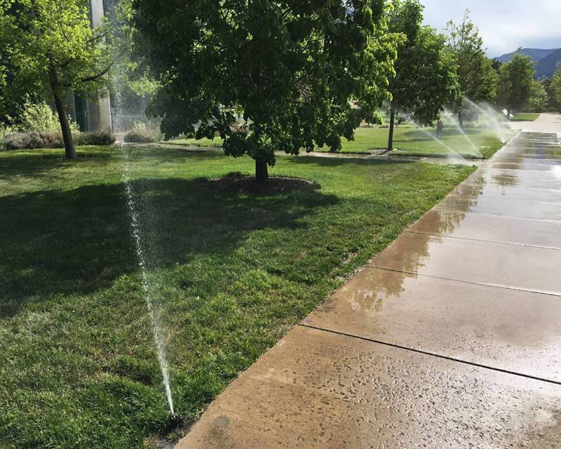
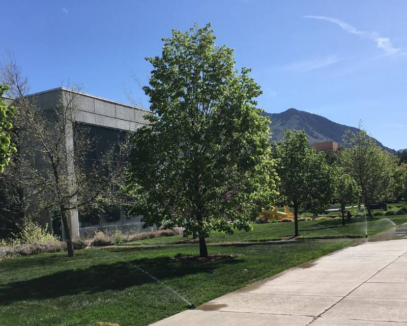
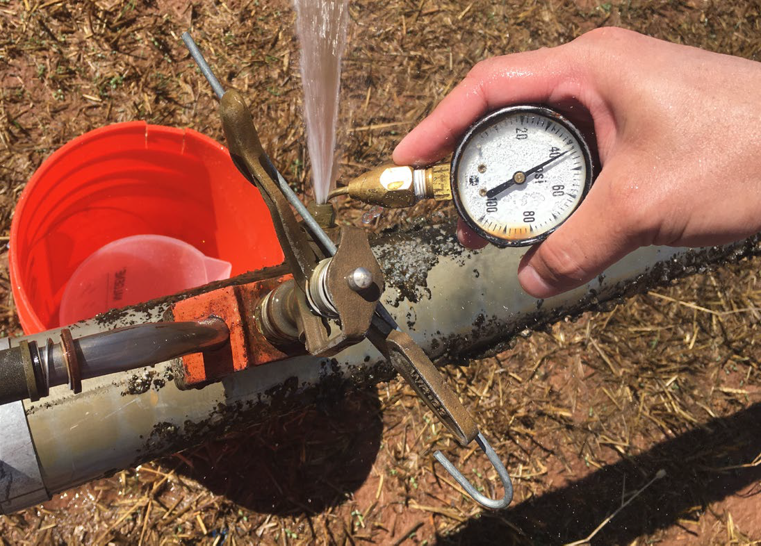
Pressure issues may be visible in sprinklers. Low pressure creates a donut-like pattern due to unbroken spray (Figure 4). Sometimes this pattern is evident in the crop being irrigated. On the other hand, too much pressure causes the spray to break up into fine droplets that do not travel far. This will cause a high application near the sprinkler and less application far from the sprinkler. Pressure at a sprinkler can often be measured using a pitot (said “pea-toe”) tube attached to a pressure gauge
(Figure 5). The pitot tube is inserted into the sprinkler’s nozzle. In drip irrigation, pressure troubles are less obvious but may appear in uneven crop production along laterals or are related to topography.
Practices to Maximize Uniformity
The irrigation system designer is responsible for designing the system to minimize pressure variation caused by friction and elevation changes while balancing the cost of the system and operation (increased pressure means increased pumping costs). However, if a system operates with an inlet pressure different from the original design, for example, then this will affect the system’s hydraulic behavior and can alter the uniformity. So, it is important to maintain the proper inlet pressure for the system. This includes proper pump maintenance and avoiding supplying more irrigation systems from a single source/mainline than originally designed.
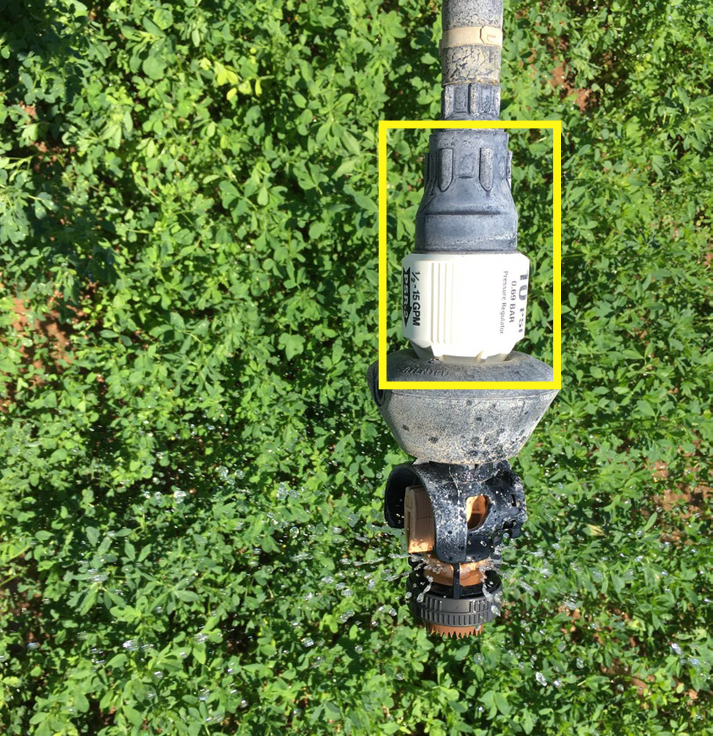
When pressure variation in a system is unavoidable, it may be helpful to use pressure-regulating valves (pressure regulators) or flow-control nozzles/emitters. Pressure regulators are valves designed to discharge a set pressure, provided the inlet pressure is greater than the set pressure plus valve losses (Figure 6; Figure 7). Small pressure regulators often have about 5 psi of loss (for example, Nelson Irrigation Corporation, 2008). Larger valves may have more pressure loss. Pressure-regulating valves may be placed on a submain or manifold, a lateral, or just upstream of individual sprinklers. Greater pressure control may be achieved by placing a regulator on each sprinkler or each drip lateral, but this may be unnecessary and should be balanced against economics accounting for proper regulator replacement.
Flow-control nozzles/emitters are smaller than regulators and are part of the sprinkler or drip emitter. These devices use a flexible diaphragm or bushing that constricts the flow area as pressure rises. The bushing constriction offsets the increased flow potential caused by pressure increases. While useful, these devices require appropriate pressure conditions and timely replacement to remain effective (Figure 7).
2. Manufacturing Variation in Nozzles, Emitters, and Other Components
Causes of Nonuniformity
Random variation resulting from the manufacturing process may cause discharge variations in sprinklers/emitters. Manufacturing variation is often reported for drip emitters but less commonly for sprinklers. This variation is more important in drip irrigation because drip systems operate at smaller pressures than sprinkler systems and have small variations in emitter performance, therefore often having more significant impacts on uniformity.
Practices to Maximize Uniformity
Typical recommendations are to select drip emitters that have a manufacturer’s coefficient of variation (CV) of less than 3%. The CV is the statistical standard deviation divided by the average; in the case of emitters, these statistics are for discharge. Ninety-five percent of the emitters of that make and model will have a discharge plus or minus 2 times the CV from the rated discharge (see example).
Example:
An emitter model with a rated discharge of 1 gallon per hour (gph) has a CV of 3%. So, take
2 × 3% ÷ 100% × 1 gph = 0.06 gph.
Ninety-five percent of the emitters will discharge between
1 gph - 0.06 gph = 0.94 gph, and
1 gph + 0.06 gph = 1.06 gph
a range of 0.12 gpm or 12%.
3. Insufficient Sprinkler or Emitter Spacing
Causes of Nonuniformity
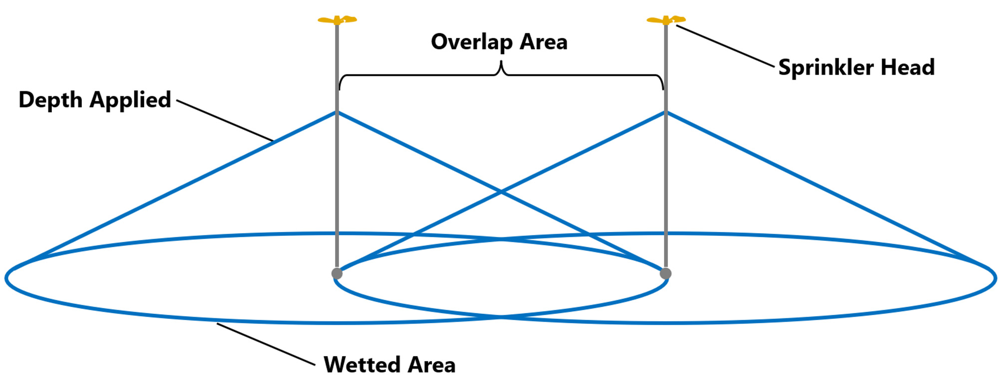
Sprinklers wet circular areas often with a cone-shaped application rate, with more water near the sprinkler and less farther from the sprinkler. To maximize uniformity, sprinklers are typically spaced close enough that the water from each sprinkler at least reaches its adjacent neighbors (Figure 8). This is called head-to-head coverage. Closer spacings are also acceptable and are the general practice for center pivots. However, except for pivots, the spacing of sprinklers/emitters along a lateral and the spacing of laterals should be consistent. When this is not the case, uniformity suffers. For drip irrigation, emitters should be spaced sufficiently close to each other so that each plant receives similar access to water. This can be challenging for close-seeded crops like small grains, pasture, alfalfa, and turfgrass.
Practices to Maximize Uniformity
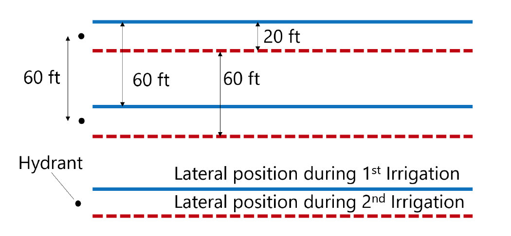
Using consistent and sufficient spacing within an irrigation system is the primary practice to avoid nonuniformity from spacing. Often, the head-to-head coverage is violated in hand line and wheel line hydrant spacing. In the case of wheel lines, this can be remedied by alternating the wheel line position by one roll from one irrigation cycle to the next (Figure 9).
4. Irrigation System Disrepair
Causes of Nonuniformity
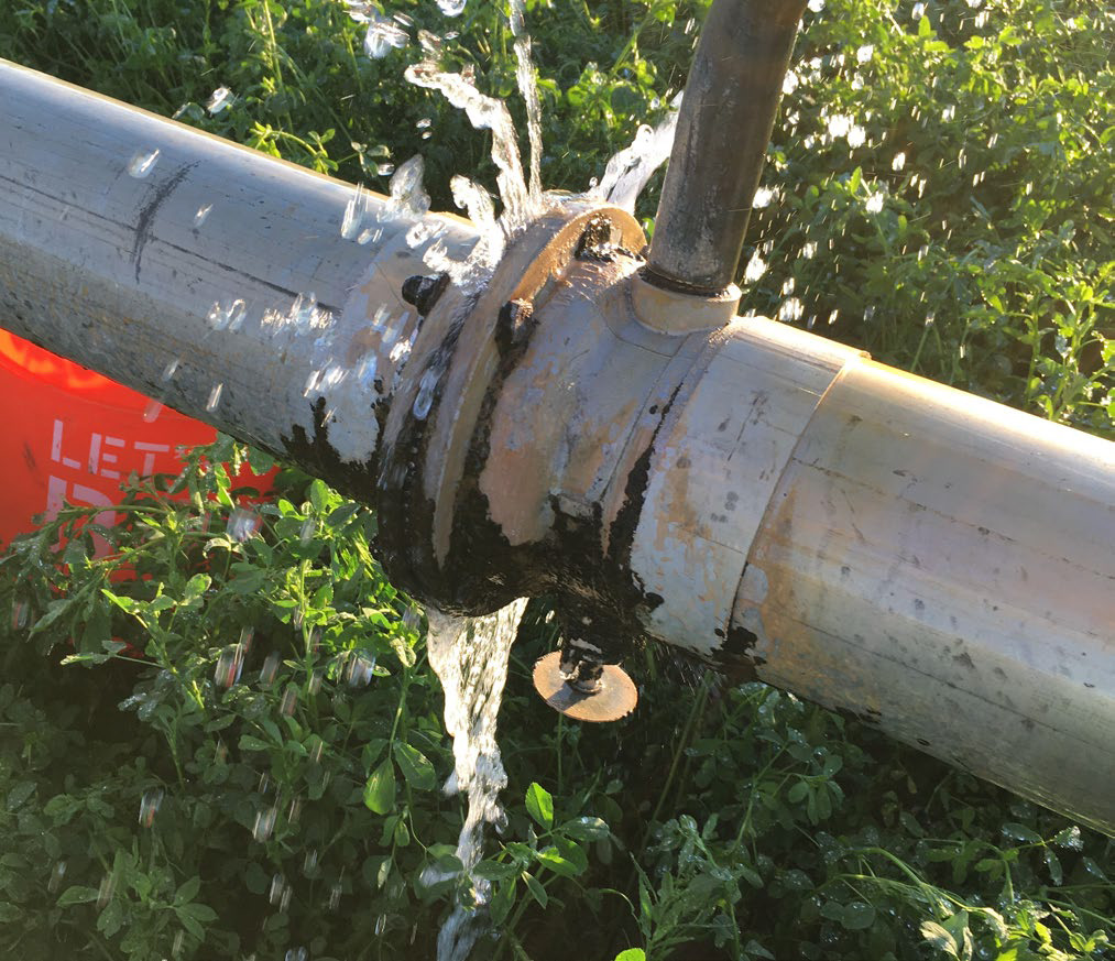
Another cause of discharge variation is the wear of nozzles and emitters. With wear, their discharge area increases, leading to higher water output at a given pressure, like Figure 2. Sometimes, nozzles/emitters are replaced with incorrectly sized nozzles, which then discharge more or less than intended. Sometimes, different sprinkler/emitter models are used, which causes variation in performance or sprinkler overlap. System leaks (Figure 10) can also cause more flow (and friction loss) in some segments of a system, which then reduces performance downstream as pictured in Figure 4. A researcher in Idaho tested 30 wheel line irrigation systems. He found that, overall, there was 26% additional water applied by those systems because of leaks and worn, incorrect, or missing nozzles (Neibling, 2015).
Practices to Maximize Uniformity
Use consistent nozzle/emitter sizes and models throughout the system, except where specifically designed to be different. For center pivots, follow the sprinkler nozzle chart when making any sprinkler repairs. Replace sprinkler nozzles at proper intervals. Some center pivot manufacturers recommend nozzle, sprinkler, and pressure regulator replacement every 10,000 hours of operation (for example, Olson, 2020). In Utah, this might be roughly every 5 years for center pivots over alfalfa and about 6 years for pasture, but it would depend on water quality. The actual operation hours should be tracked for each irrigation system.
5. Clogged Nozzles or Emitters
Causes of Nonuniformity
Nozzles/emitters may become clogged with debris or sediment.
Practices to Maximize Uniformity
To avoid clogs, it is necessary to have proper filtration. Sprinkler nozzles should include water filters to exclude particles less than one half the sprinkler nozzle diameter. For micro sprinklers, this is reduced to less than one seventh the diameter, and manufacturer filtration recommendations should be followed for drip emitters (Burt & Styles, 2016). For small sprinklers and drip, any pipe or other components made of corrodible materials should be avoided downstream of the filtration system. Use chemigation to regularly remove scaling from drip systems. Manage chemigation/fertigation to avoid precipitating solids from the chemicals and water used. Check the system regularly for clogs and unclog sprinklers promptly. To avoid sediment clogging nozzles/emitters, it is best to have sprinkler outlets and drip emitters oriented upward from the lateral.
6. Weather Conditions
Causes of Nonuniformity
Nonuniformity for sprinkler systems may be caused by water evaporation and wind drift during irrigation. These can cause different parts of a field to receive differing amounts of water depending on the time of day they were irrigated. This is not typically a problem with drip irrigation.
Practices to Maximize Uniformity
Typically, using sprinklers with larger droplets minimizes these effects in areas prone to wind and evaporation (like much of Utah). However, care must be taken because large droplets can cause soil surface sealing and irrigation water runoff. Manage irrigation so that portions of the field are not regularly irrigated at the same time of day. For example, avoid setting center pivots to irrigate in times that are even increments of a day to vary the time of day each part of the field is irrigated. If hand lines or wheel lines are on 12-hour sets, avoid irrigating each hydrant during the same part of the day two irrigation cycles in a row. Vary the time of day that micro sprinkler and solid-set sprinkler system zones operate.
7. Irrigation Duration
Causes of Nonuniformity
In many sprinkler and drip systems, subareas, zones, or sets within a field are irrigated at one time, and then irrigation is switched to another set. If, during a given irrigation cycle, the set times are inconsistent between zones/sets, the overall field irrigation uniformity will decrease. For example, if irrigation sets are supposed to take 12 hours each, but some are operated for 11 ½ hours and some for 12 ½ during the same cycle or turn across the field, field-wide uniformity will suffer.
Practices to Maximize Uniformity
Maintain consistent irrigation set timing during a given irrigation cycle or turn across a field.
8. Soil Water Infiltration Variability
Causes of Nonuniformity
The soil’s ability to infiltrate water can also cause nonuniformity if water fails to infiltrate and runs off an area within a field. Runoff causes uneven water distribution within the field. Runoff can also leave the field, not benefiting the crop. Runoff can occur in both drip and sprinkler systems, though it is more common for sprinklers.
Practices to Maximize Uniformity
Avoid runoff with sprinkler and drip irrigation systems through a combination of design and management. For center pivots, using sprinklers with a wider diameter of throw can reduce runoff risk. The primary management practice to avoid runoff is applying less water (shorter set times or faster center pivot speeds) during an irrigation event. If you observe runoff, apply less water more frequently.
Summary
Irrigation application uniformity in sprinkler and drip irrigation systems depends upon designing, maintaining, and managing the irrigation systems. System maintenance and management are the factors most controllable by a producer. Maintaining proper system pressures, regularly replacing sprinklers, using offset lateral locations, and varying the time of day of irrigation for each area of a field are primary practices for maximizing sprinkler uniformity. Proper filtration and chemigation maintenance are primary practices to maintain drip irrigation uniformity.
References
- Burt, C. M., & Styles, S. W. (2016). Drip and micro irrigation design and management for trees, vines, and field crops: Practice plus theory (5th ed.). California Polytechnic State University Irrigation Training and Research Center. http://www.itrc.org/books/dripmicro.php
- Neibling, H. (2015). Water and energy losses due to leaks and worn nozzles on set-move systems. University of Idaho Extension Kimberly Research and Extension Center. https://www.uidaho.edu/-/media/UIdaho-Responsive/Files/Extension/admin/Impacts/2015/28-15hneibling-leaks.pdf?la=en&hash=63911256A6B262BCC72465F6B6F9B7826AEBE6F9
- Nelson Irrigation Corporation. (2008). Nelson’s Universal Flo and Hi Flo regulators [Brochure]. https://nelsonirrigation.com/library/Regulator_Brochure.PDF
- Olson, A. (2020). 5 things you may not know about your irrigation sprinklers. Valmont Industries, Inc. Retrieved March 22, 2023, from https://www.valleyirrigation.com/blog/valley-blog/2019/08/22/5-things-you-may-not-know-about-your-irrigation-sprinklers.
Published April 2024
Utah State University Extension
Peer-Reviewed Fact Sheet
Authors
Burdette Barker, USU Extension Irrigation Specialist
Sheridan Stewart, USU Graduate Research Assistant
Mark Nelson, USU Extension Professor, Beaver County