009 - Managing Forests for Water Quality: Stream Crossings
Stream Crossings and Water Quality
A well-constructed stream crossing will protect water quality and fish habitat for future generations.
Crossing streams often involves disturbing, excavating, moving and compacting large amounts of soil. Soil disturbance in and around the stream can cause sediment to settle into the gravel spawning beds fish depend on for hatching their young. Increasing water temperatures associated with stream disturbance reduce the oxygen available to important aquatic organisms. Stream crossings also increase the likelihood of chemical contamination from spills and vehicles.
Reliable access to forest land is still essential to carry out management activities such as stand improvement, timber harvesting, site preparation, planting, and for recreation. Therefore, planning and location of access roads should minimize crossing streams, wetlands, and other water bodies whenever practical. Right-of-way constraints, management efficiency and stream patterns will make some water crossings necessary.
Which Type of Stream Crossing is Right?
Stream crossings can be grouped into three major categories: culverts, fords and bridges. Each type of crossing has advantages and disadvantages, and no one kind of crossing will work in every situation. When it is necessary to construct a stream crossing, consider these basic questions:
- Does the crossing need to be temporary or permanent?
- What kinds of vehicles will use the crossing?
- What are the existing stream conditions such as channel size, flow, and bank and substrate materials?
- Which type of crossing is most practical in terms of location and cost?
The following table addresses these questions by listing the advantages and disadvantages of each type of crossing.
Comparison of Culverts, Fords and Bridges
| Crossing Type | Advantages | Disadvantages |
|---|---|---|
| Culvert |
|
|
| Ford |
|
|
| Bridge |
|
|
Considerations in Construction of any Stream Crossing
Location of crossings
Planning of stream crossing sites should occur with road layout, well ahead of any construction activity. Whenever possible, a stream crossing should be located on a straight, relatively flat stream segment. Curves, oxbows or steep areas should be avoided, as locating a crossing in any of those situations may result in extra erosion and will make construction and use of the crossing more difficult. A stream crossing should always be at a right angle to the stream.
Timing of construction activities
Time stream crossing construction activities to minimize impact to water quality. This usually means working in late summer when water flows are minimal, although flash floods from thunderstorms must be considered. If the stream is fish-bearing, the impact to the fishery must be accounted for. Place stream crossings as quickly as possible to limit adverse impacts. Divert stream flow through temporary culverts or conduits while culverts are installed. The size of the diversion culverts or conduits must be able to accommodate flows from flash flooding.
During the construction of any type of stream crossing, erosion must be controlled. This can be done by installing silt fencing or using hay bales to catch sediment. If stream banks are sufficiently disturbed during construction, seeding and/or placement of protective rip-rap may be necessary to prevent erosion after construction.
Streambank alteration permit
Anyone planning an activity that will affect a natural stream must first obtain a Stream Alteration Permit from the Utah State Engineer’s Office. The State Engineer’s working definition of a natural stream is “any natural waterway in the state which has flows of sufficient duration to develop a characteristic ecosystem distinguishing it from the surrounding environment.” To obtain permit application materials, contact Utah Division of Water Rights at 801-538-7375, or at their website.
Streamside Management Zones
All stream crossings will fall within the streamside management zone (SMZ), a strip of land adjacent to any stream within which protection of water quality is critical. For a discussion of SMZs and recommendations for forest practices within SMZs, see Utah Forest Facts NR/FF/008, Managing Forests for Water Quality: Streamside Management Zones. Erosion control
Culverts
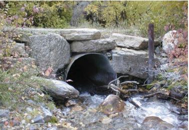
Waterfalls from culverts scour the stream bed and make fish passage difficult. Aligning the culvert with the stream gradient is the preferred practice, although rock armoring can be used here below the waterfall to reduce scouring and above the culvert to reduce road erosion.
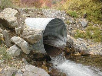
Culverts are the most commonly used form of stream crossing. Culverts are made from metal, concrete, polyethylene pipes or wood boxes. An operator sets a culvert in the crossing and the stream flows through it. A culvert is easily placed, functions well, is relatively inexpensive and can be reused upon removal when no longer needed.
Culverts should be of sufficient size to accommodate peak runoff and flood waters. The size of the culvert for a temporary road crossing should allow for the highest daily water flow from the largest storm that has occurred in a 25 year period (known as the 25 year – 24 hour storm event). A permanent road crossing culvert must allow for a 50 year – 24 hour storm event. Either way, minimum culvert size should be 15 inches in diameter. Installations of culverts larger than 6 feet in diameter should be designed by an engineer or hydrologist. If the stream is fish-bearing, size and placement of the culvert must allow for fish passage; the outflow of the culvert should never create a waterfall. Stream characteristics can be difficult to determine; a hydrologist may need to assess high water flow levels and/or the need for fish passage.
If possible, install and remove culverts when the streambed is dry. In a flowing stream channel, use sediment basins, a temporary diversion channel or a pump to divert water during installation and removal. When planning a culvert installation, anticipate maintenance costs, and set inspection and maintenance schedules. A plugged, dislocated or failed culvert can cause flooding, bank erosion, scouring, or sedimentation, any of which decreases the water quality of the stream.
Recommended Culvert Practices
- Culverts should be aligned with the natural stream channel. Any deflection from the stream channel will cause bank erosion. Culverts that are skewed are more prone to plugging by debris.
- Stream gradients should not be changed when installing culverts. A pitch of 2-3 percent (a drop of 2 to 3 feet over 100 feet horizontal distance) will help the culvert to be self-cleaning.
- The bed for the culvert should be made of gravel free of large rocks to allow the even distribution of the load over the full length of the culvert.
- Culverts should be placed slightly below the natural stream bed to prevent erosion below the outlet. If the outlet must be above the natural stream bed, armor the outlet with rocks, logs or other material to dissipate the energy of the falling water.
- Extend the culvert at least 1 foot beyond the fill at both inlet and outlet ends.
- Cover tops of culverts with at least 12 inches of compacted fill for culverts up to 36 inches in diameter. Cover larger culverts with a thickness of fill material at least one-third the culvert diameter. This minimizes damage to culverts from heavy vehicles and road maintenance activities.
- Firmly pack material around culverts, especially the bottom half, to anchor them and prevent them from washing out.
- Use trash racks or inlet grates where debris may threaten the structure.
- Place rock armoring or rip-rap around the culvert inlet and outlet to prevent erosion due to turbulent water flow. Rip-rap is most effective when placed on top of geotextile material.
- Inspect culverts often and clean as necessary
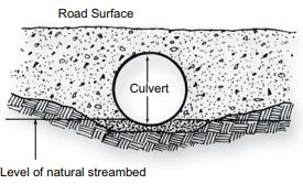
A properly installed culvert results in no change in the level of the stream bed.
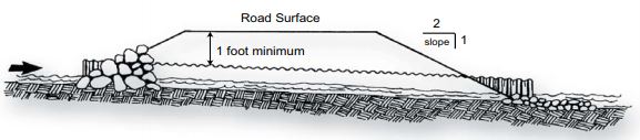
Fill over a culvert should be the greater of 1 foot deep, or 1/3 the diameter of the culvert.
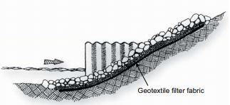
Geotextile fabric can used to support rip-rap or armoring while allowing water to drain through.
Determining Proper Culvert Size
- Determine the channel area. Measure the width at the high water mark (see below) and maximum depth of the stream channel to the nearest foot. Multiply the width and depth measurements to determine the channel area. Repeat this process three times at different locations and use the average of the three areas as the channel area
- Allow for additional area to accommodate higher than average flows. This corrected channel area figure will be the one you use to determine the proper culvert size. To do this, multiply the channel area (from Step 1) by 1.2 (thus adding 20% to the channel area).
- The minimum size pipe needed to pass the normal high flows must have a cross-sectional area that is as much or more than the corrected channel area determined in Step 2. Select the next larger pipe size to match the area of the stream (see table below).
Channel Areas and Culvert Sizes
| Area (square feet) | Pipe Diameter (inches) |
|---|---|
| 1.25 | 15 |
| 1.80 | 18 |
| 3.14 | 24 |
| 4.90 | 30 |
| 7.07 | 36 |
| 9.60 | 42 |
| 12.57 | 48 |
| 15.90 | 54 |
Locating the High Water Mark
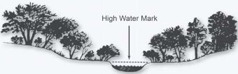
The high water mark is the point on the bank or shore up to which the presence and action of water has left a distinct mark either by erosion, impacted land vegetation, or other characteristics such as debris lines.
Fords
Fords generally are the least expensive alternative if conditions allow, as a ford is simply a stream crossing without a structure or culvert. They can be used where stream banks are low and firm, the stream bed is also firm and the stream is shallow. A stable, rocky portion of the stream channel is the best location for a ford. Fords should not be used if significant alteration of the stream bank is required. Rock, gravel or geotextile material may be used to stabilize the stream bed approaches. Concrete planks or other similar materials may be placed in stream beds or flow areas of intermittent watercourses when warranted to protect the stream bed. However, such materials must be carefully bedded to avoid trapping sediments on the upstream end.
Type of stream bed, anticipated number and weight of vehicles using the ford, and season of use should all be considered when contemplating a ford stream crossing. Fords may be the most practical alternative in areas prone to flash floods. Fords may, however, cause continued disturbance to the stream bed. Use particular care to prevent the stream from being diverted onto the road surface by the ford.
Recommended Ford Practices
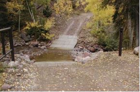
This ford on the headwaters of the Weber River has a firm rock bottom and the approaches have been hardened with concrete.
- The stream bed should have a firm rock or coarse gravel bottom and low grade approaches stable enough to support traffic.
- Traffic should be limited to low volumes of light vehicles.
- Stream water depth should be less than 3 feet.
- Crossings should be made at right angles to the stream.
- Maintain the natural level of the stream bed to let fish pass over the crossing.
- Stabilize approaches using an appropriate type of geotextile covered with clean rock. Material should extend at least 50 feet on both sides of the crossing if soft soil conditions exist.
Geotextile: Useful in Many Stream Crossing Applications
Geotextile is a synthetic engineered fabric which provides exceptional strength and stability when placed over soil, gravel or fill, yet allows drainage through the material. Generally, geotextile is placed over soft surfaces and then overlaid with gravel (vehicles should not drive directly on the geotextile surface). The geotextile allows water to flow through the gravel and fabric while keeping the underlying soil from working up through the fabric and preventing gravel from being pushed down into the soft soil. Ruts and erosion are significantly decreased with the use of geotextile. Geotextile can be woven or non-woven, and is available in a variety of thicknesses, widths and compositions. Suppliers of geotextile material in Utah include:
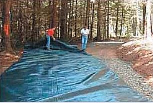
Geotextile fabric is laid over soft soil on a wet, rutted road. It will be covered with gravel to strengthen the roadbed. Photo courtesy of College of Forestry, Oregon State University.
WR White Supply
1625 Wall Ave
Ogden, UT 84401
(801) 394-6621
Geo Dynamics
2463 South 3500 West
Ogden, UT 84404
(801) 541-4788
Contech Construction Products
1935 N 900 W
Salt Lake City, Utah 84104
(801) 363-3873
Bridges
Bridges can be used for temporary or permanent stream crossings. Usually, permanent bridges are used for larger streams or for permanent roads. A licensed engineer should be consulted to help design a safe, appropriate permanent bridge. Temporary bridges are used for smaller streams and infrequent or one-time access, and can be made of various materials or devices. Types of temporary bridges include logs, sawn timber bridges and PVC/ HDPE pipe bundles.
Timber bridges can be of several types. Temporary ones could be a log stringer bridge built from local site materials, or a solid-sawn stringer bridge built from new lumber, railroad ties or recycled large timbers. A more permanent structure might be a panel bridge constructed from stress-laminated, glued-laminated, dowel-laminated or nail-laminated lumber. PVC (polyvinyl chloride) or HDPE (high-density polyethylene) pipes bound together with cables and placed on geotextile material can be a relatively inexpensive and easy way to construct a temporary bridge. Pipes are cabled together and layered on top of geotextile fabric set in the streambed. Wood mats, wood panels or other materials are placed over the pipes to add stability and traction. Water flows through the pipes while vehicles travel over them. HDPE pipes are recommended over PVC because they tolerate the cold better and do not need protection from sunlight. Pipe bundles can be used for crossings less than 10 feet wide and 4 feet deep.
Ice Bridges
Winter provides an opportunity to conduct harvest operations in areas which might be sensitive when not frozen. Snow can provide winter-time support across wet areas which would be deeply rutted if logged during the summer months. Ice bridges can be built by pushing and packing snow into streams and then applying water to freeze the structures solid so vehicles can drive across. The bridge should be thick enough to permit a level approach and support the weight and speed of anticipated traffic. Installation of an ice bridge should begin only after stream flow has slowed or stopped in winter, and it must melt or be carefully removed before water flow starts in the spring. Ice bridges should be inspected often, since weather and water flow can affect strength.
Forest Water Quality Guidelines
Utah’s Forest Water Quality Guidelines (FWQGs) are a collection of voluntary, field-applicable practices for use during forestry activities to protect soil and water resources. They are designed to minimize non-point source pollution such as sedimentation and erosion associated with forestry activities. For more information about the FWQGs and their application, contact your local Forestry, Fire and State Lands area office. A technical guide of the FWQGs is available.
Funding for this fact sheet was provided in part by the Environmental Protection Agency.
Published November 2004.