
Part I: Drip Tape Irrigation for Cut Flowers
Overview
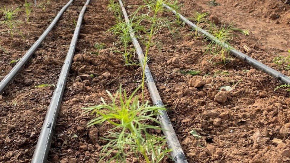
Drip irrigation can be the most efficient method for delivering water and has the added benefit of keeping moisture off foliage and blooms of cut flowers. This fact sheet is the first in a series of irrigation fact sheets for cut flowers. It provides a step-by-step guide to the initial selection and installation of a surface drip tape irrigation system. Descriptions of and considerations for common components, setup, management, and repair are discussed. While this content may apply to other horticultural and garden plants, this fact sheet was developed for cut flower crops and growers. We recommend USU Extension resources specifically for vegetables, fruits, and trees when needed.
Configuring a Drip Irrigation System
Connecting to a Water Source
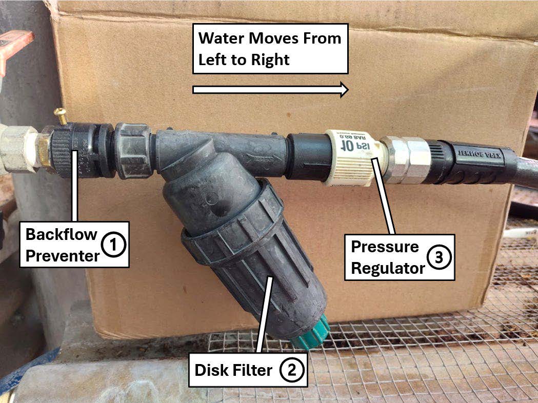
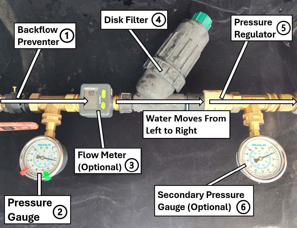
The first step in laying the groundwork for a drip irrigation system is to identify a reliable water source. In Utah, culinary (drinking) water is available for use year-round. Secondary water may be available for those with access and water shares, but use is limited to the growing season, with start and end dates varying by region. Using secondary water is often less expensive than culinary water, but this water is not typically treated or filtered for use with drip irrigation systems. Therefore, filters and more frequent maintenance are required with secondary water (as covered later in this fact sheet). Connecting a drip irrigation system safely and effectively to a water source requires a minimum of three components (illustrated in Figure 1):
- A backflow preventer is the first component that connects to a water source. This will prevent back-siphonage (negative pressure) during sudden pressure drops, such as municipal lines breaking. It is required for culinary water sources but may not be required for secondary water; the rules depend on the provider. Though the barrier mechanism varies by product, atmospheric vacuum breakers and double-check valve assemblies are common. Without a backflow preventer, soil or applied products, such as fertilizers, could contaminate the water supply.
- A filter is installed next to prevent debris or other contaminants from clogging the drip tape. Screen filters and disk filters are typically used with drip irrigation; screen filters with 140 mesh are common. Larger mesh numbers filter out smaller material; drip tape will include a recommended minimum mesh. Disk filters have more surface area and need less frequent cleaning. Systems operating on secondary water may require more frequent filter cleaning and maintenance, whereas those on culinary water may require less. Timely cleaning avoids debris buildup and maintains water pressure. Without clean filters, drip emitters clog and water delivery is hindered; the pressure, flow rate, and uniformity decrease. Once clogged, emitters often cannot be unclogged.
- A pressure regulator is the last component before the drip irrigation system can be fully installed. Pressure regulators are not designed to maintain constant pressure but to reduce and stabilize the pressure of the incoming water source, which in most instances is too high. The pressure is typically reduced to 10-15 PSI to meet drip tape specifications (Gunnel, 2025). Products typically have the PSI rating written in bold on the side. Some may list “bar” as a metric unit alternative to PSI. It is important to look for either unit of measure when selecting a pressure regulator. Typical values will be 10 PSI (0.69 bar), 12 PSI (0.83 bar), and 15 PSI (1.03 bar). If water pressure exceeds 15 PSI, drip tape lines may be damaged and even burst (culinary water sources are often 50 PSI or more). Drip tape will not work properly at a pressure lower than 6 PSI. Pressure regulators are placed after any electronic or solenoid valve. Most solenoid valves require higher pressure for proper function and will decrease the pressure slightly afterward. Manual valves can be placed after the pressure regulator but are generally recommended to be before the regulator.
Zoning and Installing Header Lines
Component Selection and Description
Dividing drip irrigation systems into individually controlled zones can address pressure constraints and homogenize water delivery across multiple locations on a property. Creating multiple zones also increases flexibility and improves water conservation. Each irrigation zone can be tailored to the water demand of the crops in the zone by species or type, density, growth rate, and production timing.
The available pressure, emitter flow rate, spacing, and diameter determine the length and number of active lines the system can support, as well as the sizing or area per zone. Consider creating zones based on system logistics, crop water demand, crop seasonality or production timing, irrigation frequency and duration, and site conditions (Schuch, 2006). For example, dahlias and water-wise perennials, such as echinacea, should be zoned separately because of their dissimilar water needs, allowing water to be reduced in zones with low-demand plants. Properties may also vary by soil texture (i.e., proportion of sand, silt, clay minerals), which influences water infiltration rates, irrigation demand, and water storage. Zoning these sections appropriately will prevent uneven water distribution and irrigation. See USU Extension fact sheet, “Part II: Sustainable Practices for Cut Flower Irrigation” for classifications of cut flower crops by water demand and recommendations for irrigation practices by soil texture. Sloped areas and sites with different sun exposure should likewise be managed as separate zones (Whiting, 2017).
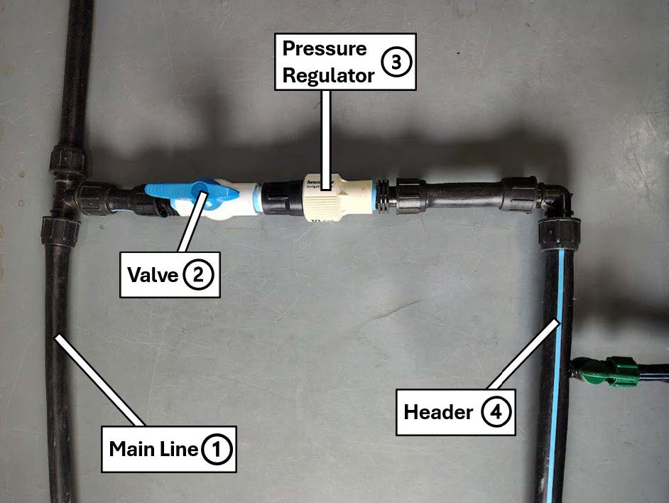
Directing water to each zone may require a main line to connect to a header (Figure 2), along with a series of parts, described and pictured in Table 1:
Table 1. Components That Connect a Drip Tape Irrigation System to a Water Source Connection
Main linePrimary tubing line is made of PVC, polyethylene, or metal. The diameter should match system flow and field size, commonly 1 inch. Other common sizes are ¾ inch or 1½ inches. |
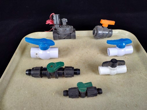
ValveManually controlled or automated to turn on at a specific time or run for a set period, they should match the diameter of the main line. Typically, small-scale systems use ¾ to 1 inch; larger systems use 1¼ to 1½ inches. |
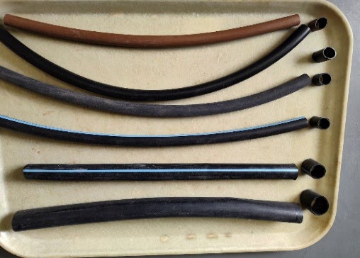
Headers and subheader linesPoly pipe tubing distributes water to drip tape lines. The length of tubing and flow rate depend on pipe diameter. Small-scale sizes are typically ½ inch, supporting 3 GPM over 200 feet of run length, and ¾ inch, supporting 8 GPM over 480 feet of run length (Drip Depot, 2021). |
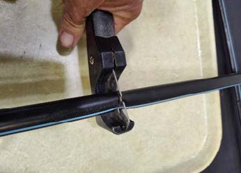
Tube cuttersThis specialized tool cuts poly pipe (knives and scissors can leave jagged or uneven cuts). It is designed to produce straight, clean cuts for properly fitting connections. |
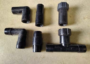
Compression fittingsThese fittings connect tubing and must match the tube outside diameter (OD). An incorrect size can result in a poor seal. Common sizes in drip tape systems include ½, 0.62, 0.71, or 0.72 inches. |
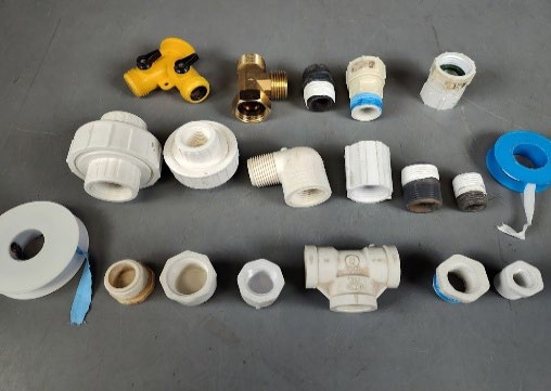
Threaded fittingsThese connection components have threaded ends that must match the nominal tubing size, not the inside diameter (ID) or OD, and can be sealed with PTFE tape (typically 1/2 and 3/4 inch for drip tape systems or larger). |
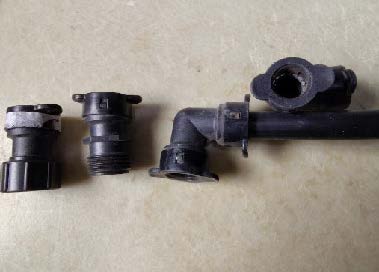
Bite-type fittingsFittings are used to connect poly tubing by gripping the tube and should match the OD of the tubing. The most common size is ½ inch, and larger ¾- to 1-inch sizes are available. |
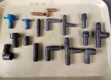
Barbed fittingsFittings are used to connect flexible tubing using barbed ends. Flexible tubing may allow some mismatch, but should be installed to the exact ID. Diameters include ½, ¾, or 1 inch. |
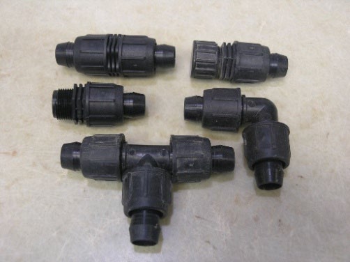
Locking-nut compression fittingsThese fittings are used to connect tubing using a locking-nut mechanism and must match the tube OD. Available sizes include ½, ¾, or >1 inch. |
- A main line is needed to carry water from the source to the designated field. It is required for fields far from a water source but otherwise may not be needed. Main lines can be made of PVC, polyethylene (i.e., HDPE or poly pipe), steel, or aluminum tubing. If steel tubing is used, filtration may be needed after to prevent rust flakes from clogging emitters.
- A valve can separate irrigation areas into zones and is either electronically automated or manually operated. A pressure regulator is required per zone to reach the correct pressure for the drip tape. The combination of a valve with a pressure regulator is the pre-assembly component in a field before a header is introduced. A pressure regulator should not be placed downstream of another pressure regulator. For example, if using a regulator for each zone, do not include one earlier in the system. The pressure regulators will only maintain the labeled pressure if the pressure going into the regulator is more than 5 PSI greater than the regulator rating.
- Headers come after the pressure regulator and are the main water distribution lines that deliver water into the drip tape lines. They are made of low-density poly tubing that typically runs in straight lines. Bent header lines can break or cause water to be disproportionately distributed in the system. Angled lines are possible but may cause inconsistencies in parallel drip tape lines or add complexity to lateral drip line installation. A specialized tube cutter is used to cut the header to size and ensure clean, straight cuts for poly tubing.
- Subheaders are smaller pipe/tubing sections connected to the main header to help maintain pressure that would otherwise be lost through friction from water traveling longer distances. They can be configured into “branching” subsections that simultaneously address space constraints or obstructions that block the header's direction. Other benefits include improved zone optimization to ensure the proper volume of water is applied.
Fittings
Provide controlled routing for header lines, extending lines, or redirecting lines to avoid bending tubing or driplines. All types of fittings, although differentiated by their unique mechanisms of installation, share features that redirect or adjust the amount of water applied. A tee is “T”-shaped, and an elbow is “L”-shaped, and both provide redirection at a 90-degree angle. Couplings are straight-line connectors that connect header lines of the same diameter. Reducers are used as transitional connectors for different-sized tubing. End plugs are used to close off the ends of tubes and drip tapes. Additional product specifications are in Table 1.
- Compression fittings press onto tubing and are secured by compression. Parts connected to poly tubing can be male (M), female (F), or a combination of the two. The header diameter must match the fittings. These fittings are single-use; detaching them will leave permanent deformation in the tubing, making it unusable.
- Threaded fittings are either male or female components, and both are required to make a connection. Male fittings have threads on the outside, like a bolt, and female fittings have threads on the inside. These fittings can either be (1) tapered threaded pipe--American National Standard Taper Pipe Thread (NPT), like common pipe fittings, or (2) parallel or straight threads--American National Standard Straight Pipe Thread (NPS), like hose bib threads. Pipe and hose threaded fittings are not compatible with each other because of different sealing methods. Connecting a pipe with a hose thread will require an adapter. This is especially important with various ¾-inch fittings. Hose-threaded fittings are sealed with a gasket or O-ring, while pipe-threaded fittings require PTFE (polytetrafluoroethylene, or Teflon®) tape to lubricate the threads for a proper seal.
- Bite-type fittings connect to tubing via a built-in ring that grips the tubing to create a water-tight seal. Though similar in appearance to compression fittings, they are distinguished by the teeth inside and are all female connectors. They are push-in and quick to install, but have a higher upfront cost compared to other fittings.
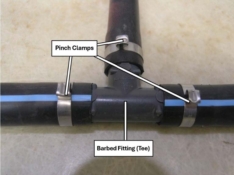
- Barbed fittings are a relatively inexpensive type of connector without a screw seal. The ridges are directly inserted into the pipe, creating a friction seal. An advantage is that they can be used with a pipe with a slightly different inside diameter (ID). Barbed fittings are prone to leaking or can come undone, even in low-pressure systems. They may require clamps to ensure a tight seal to prevent leaking or blowing out (Figure 3).
- Locking-nut compression fittings go by various names depending on the seller. They resemble barbed fittings but the key difference is that barbed fittings force tubing over their ridges, while nut-type fittings compress the tubing against their lock. These fittings must match the outside diameter (OD). The nut must be twisted to compress the tubing against the internal bell insert. They are easy to install, but have a higher upfront cost. These types of fittings are most common for drip tape systems.
Supplemental Components for Fittings
Not all fittings require additional steps for installation, and many are reusable until damaged. Others may require supplementary parts that can prolong installation or incur additional costs. This section briefly covers common tools and components, with additional information in Table 2.
Table 2. Water Supply and Initial System Distribution Components
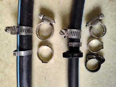
ClampsUsed with barbed fittings, these maintain a secure connection. Available as hose (worm gear), ratchet (reusable), and pinch (crimp, single-use) clamps. Sizes correspond to ODs. Hose clamps and pinch clamps are stainless steel, whereas ratchet clamps are made of plastic. |
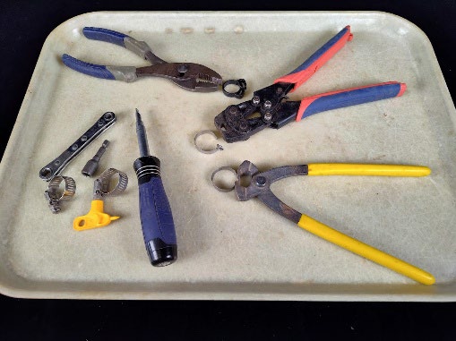
Securing hardwareTools are used to fasten clamps onto barbed fittings. Pinch clamps require crimping pliers, hose clamps require a socket wrench with a ¼- to 5/16-inch hex, and ratchet clamps require standard pliers. |
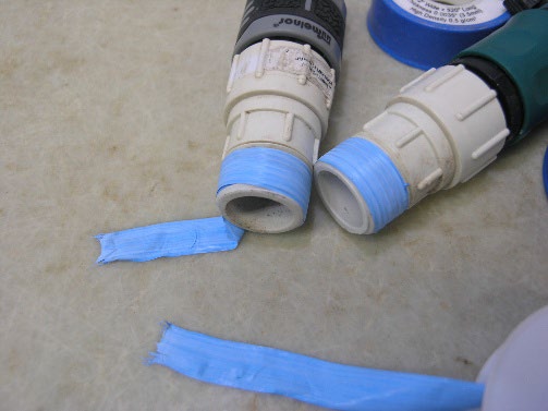
PTFESealing tape is used for pipe-threaded fittings only and should not be applied to hose-threaded fittings. Common widths include ½, ¾, and 1 inch, with 3 mil being the most common thickness; a heavy-duty 4–5 mil option is also available. |
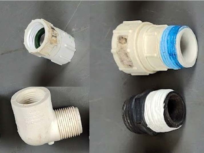
AdaptersThese components may be male, female, or a combination of both, and must match the thread type and nominal size of the connected pipe or fitting. If the nominal size does not match, a poor seal may result. Common adapter sizes include ½, ¾, and 1 inch. |
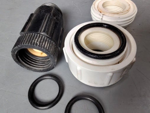
O-RingsThe ID should correspond to the size of the groove in the hose-threaded fitting. Typical O-ring sizes may range from ½ to 1 inch ID, with common ODs of ⅝ and ¾ inch and thicknesses of ⅛ or 1/16 inch. |
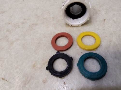
GasketsAlso referred to as hose washers, these are sealing components used in ¾-inch, hose-threaded garden hose fittings. They typically have an OD of 1 inch and a thickness of ⅛ inch and are standard for ¾ inch hose-threaded garden hoses. |
- Clamps are a complementary addition to barbed fittings, ensuring a tight seal and preventing leaks or breakage. Types of clamps include hose clamps (worm gear), ratchet clamps, which are reusable, or pinch (crimp) clamps that are of one-time use, to name a few.
- Securing hardware is required to ensure that clamps are properly installed to barbed fittings. If pinch fittings are used, then tubing clamps are required. They are also referred to as crimping pliers. Socket wrenches are used to tighten hose-clamps, whereas ratchet clamps can be installed by hand or, if necessary, by using standard pliers.
- PTFE tape, or polytetrafluoroethylene tape, is primarily used for threaded fittings to create tight seals and prevent leaks within fittings. Other names referring to PTFE include Teflon® tape or plumber’s tape. Using PTFE is not required for hose threaded parts.
- Adapters are used to connect incompatible fittings. They can be either male or female or a combination of the two. A pipe-to-hose threaded fitting will primarily require an adapter to create compatibility.
- O-Rings are a round seal for straight-threaded connectors. They can only be applied in female fittings with a groove inside, to ensure that once the male fittings are applied and compressed, they create a tight seal.
- Gaskets, or flat washers, are similar to O-rings and ensure the male fittings create a tight seal once compressed. A key difference between gaskets and O-rings is when to use them, which is when the female hose threaded part has a flat seat inside. They are not meant to be used on male fittings. They are commonly used in hose-bib fittings.
Selecting Drip Tape
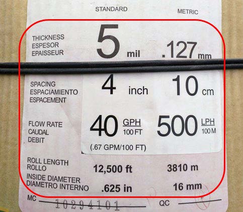
Selecting drip tape depends on the property, system capacity, and crops. Consider the number of beds, length per bed, number of drip tape lines per bed, soil texture, row and plant spacing, plant water requirements, and desired durability. Then, use the drip tape specifications to optimize efficient and effective water distribution: the flow rate, emitter spacing, diameter, and wall thickness.
Flow rate specifies the volume of water, in gallons per unit time. These units are gallons per minute (GPM) or gallons per hour (GPH) per 100 feet (Figure 4). In addition, the water released per emitter (GPH) may be listed. Note that drip tape can be categorized by low, mid, and high emitter flow rates, but is normally described by the flow rate per 100 feet.
- Low flow: less than 0.25 GPM per 100 feet. This allows for slow infiltration, making it the ideal choice for clayey or poorly drained soils and when multiple drip lines are used close together, rather than just a single higher flow line. Low flow provides a better opportunity for water to redistribute in the soil. Low flow also improves the uniformity of water delivery over longer fields that have drip tape lengths beyond 380 feet because the tape flow rates are lower. The main drawback is the long irrigation durations to deliver the proper volume of water. This can be a challenge with multiple zones that need to run consecutively, or with limited time or access to water turns. Low-flow drip tape may require a filter with a higher (smaller) micron rating to reduce the likelihood of sediment buildup at the emitters. This is because the emitters are smaller than for higher flow tape and clog more easily.
- Medium flow: ranges from 0.30 to 0.67 GPM per 100 feet. This is ideal for loamy soils and where drainage is adequate. Drip tape from most kits will be in this range. Run times are shorter than those of low-flow tape, allowing for more flexibility in scheduling each zone’s irrigation.
- High flow: greater than 0.8 GPM per 100 feet. This tape provides the greatest volume delivered in the least amount of time. This is not appropriate for soils that cannot infiltrate the water quickly enough, as it will result in puddling and surface runoff. Because of the high flow rate, it cannot be used for long irrigation cycles. High-flow drip tape is normally used in small areas for short irrigation cycles, like in high tunnels or small flower beds. Higher flow tapes also increase the potential to overirrigate if run times are too long.
Emitter spacing is the distance between emitters, or the holes in the drip tape lines that release the water. Spacing is typically given in inches and ranges from 4 to 60 inches. Spacing between emitters is important to consider in relation to soil type and crop spacing (Table 3). Emitters spaced too far apart may miss some plants, cause puddling, or result in water percolating deeper than the root zone. Emitters spaced too close are less of a problem but may be inappropriate if plants are not closely spaced in the row.
Table 3. Cut Flower Crops Grouped by Plant Spacing: Close (light green), Medium, and Distant (dark green)
| Crop1 | Crop spacing (in.) | Drip tape line distance from crop (in.) | Emitter spacing (in.) |
|---|---|---|---|
| Close plant spacing | |||
| Anemones | 6 | 2–4 | 6 |
| Larkspur | 6 | 2–4 | 6 |
| Lisianthus | 4–8 | 2–4 | 3–6 |
| Mini carnation | 6–9 | 2–4 | 6 |
| Ranunculus | 6 | 2–4 | 6 |
| Snapdragons | 4–6 | 2–4 | 4–9 |
| Stock | 6 | 2–4 | 6 |
| Medium plant spacing | |||
| Bells of Ireland | 10–12 | 2–6 | 8–12 |
| Celosia | 10–12 | 2–6 | 8–12 |
| Delphiniums | 12 | 2–6 | 8–12 |
| Dusty miller | 10–12 | 2–6 | 8–12 |
| Statice | 8–12 | 2–6 | 8–12 |
| Sweet pea | 8–12 | 2–6 | 8–12 |
| Zinnias | 10–12 | 2–6 | 8–12 |
| Distant plant spacing | |||
| Cosmos | 12–18 | 2–6 | 12 |
| Dahlia | 18–24 | 3–6 | 4–18 |
| Echinacea | 16–24 | 3–6 | 8–18 |
| Echinops | 16–24 | 3–6 | 8–18 |
| Eryngium | 16–24 | 3–6 | 8–18 |
| Peony | 24–26 | 3–6 | 4–18 |
Note. Drip tape recommendations assume one drip line per crop row.
1Source: Small Farms Lab, 2026
Wall thickness varies depending on the conditions it will be exposed to, such as UV exposure, temperature fluctuations, soil disturbance, crop residue, insects, animals, field management, tape handling, and desired longevity. Thinner lines are 4 to 6 mil (mil is 0.001 inches), medium lines are 8 to 10 mil, and heavier lines are ≥ 13 mil. Thinner lines are expected to be used for a single crop season because they have poor durability, making them prone to damage. They also have a lower upfront cost and can be practical for fields with annual rotations and field operations, such as tillage, when the drip tape must be removed. Heavier drip tape offers greater longevity, durability (multiple years), and damage resistance, but has a higher upfront cost. It works well in beds with perennials or minimal disturbance. In beds with annual field operations, drip tape with a greater wall thickness may require careful removal and storage.
Bed size and crop spacing determines the number of drip tape lines per bed for optimal irrigation. A general recommendation is 4 feet wide for narrower production beds, which allows hand access to the interior for weeding, harvest, and other maintenance. In most cases, only one line of drip tape is installed for each crop row. The lines are placed within a few inches of the crop row and run adjacently. For crops with very close spacing (e.g., 3- to 4-inch), one drip line may support more than one row of crops. Reference Table 3 for crop categories by row and drip tape line spacing.
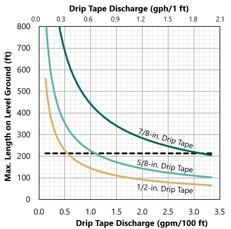
Inside diameter that is larger handles greater flow rates (larger run lengths) and provides more uniform pressures and water delivery. However, larger diameter costs more than smaller diameter drip tape. See Figure 5 for recommended maximum lengths for different drip tape sizes on level ground. Allowable run lengths may increase on gentle, downhill slopes. Allowable run lengths typically drop by 15 to 60% for uphill running drip tape, as friction and gravity reduce the pressure of the water moving up slope (Sandford et al., 2018).
Connecting the Drip Tape to a Header
Broadly, to attach drip tape to a submain or header, a take-off connector is used (Figure 6), while the end of the drip tape is secured with an end connector. A full list of drip tape tools and components are shown and described in Table 4.
Table 4. Drip Tape Line Components and Tools for Attaching, Redirecting, and Addressing Layout Challenges
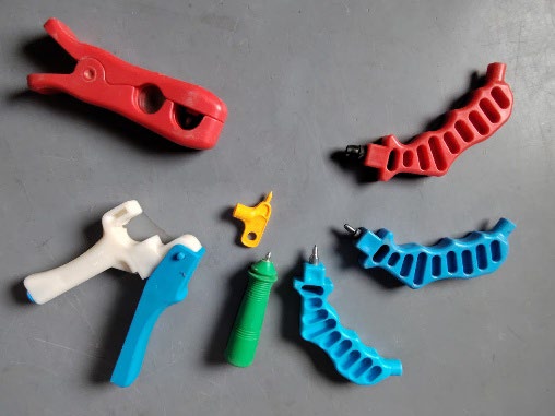
Hole punchThis specialized tool makes holes in main headers for drip tape take-off connectors. Headers often have a blue or purple line to keep holes aligned and straight. Hole punches are compatible with polyethylene headers and other plastics. |
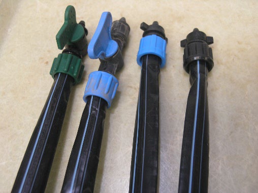
Drip tapePolyethylene tubing supplies water to crops. Key specifications include flow rate (GPM or GPH), emitter spacing (in. or cm), wall thickness (mil), recommended PSI, and diameter (in. or mm). A diameter of ⅝ inch is common for drip tape lines. |
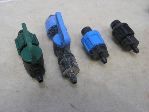
Take-off connectorsThese distribute water from the main header to the drip tape lines. Most common types do not include a valve; versions with a valve are referred to as shut-off valves. Common sizes match the drip tape ⅝ inch and the header hole punch size of ¼ inch. |
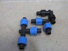
Elbow and tee connectorsUsed to redirect drip lines into other sections, available tee connectors are “T” shaped and elbow connectors are “L” shaped. Common sizes match the drip tape ⅝ inch. |
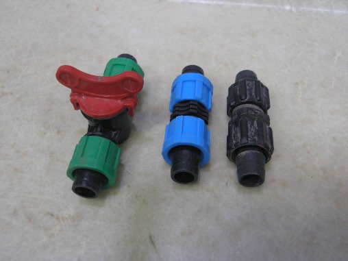
CouplingsCouplings reconnect damaged drip lines. Versions with a valve are referred to as shut-off valves and allow for segregated water application in beds. Common sizes match the drip tape ⅝ inch, and the area available without a valve. |
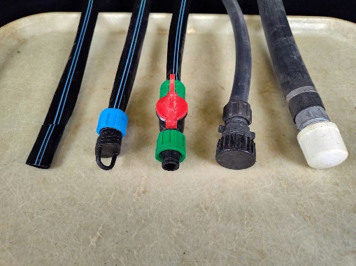
End connectorsThese stop the water flow at the end of the drip line. Tightening is important, as leaks can occur at these primary connections; drip line knots are not recommended and should only be used for emergencies. |
A hole punch is used to make holes in the poly pipe where each drip tape line connects to the header line. Hole punches are typically sized ¼ inch. The insertion hole made to the header is between 2 and 3 mm (1/16 to ⅛ inch), and not ¼ inch. The ¼-inch size measurement for the hole punchers is intentionally smaller than the barb diameter of the connectors to ensure a tightly formed seal. Larger hole punchers are available for larger take-off adapters but are primarily used for ¾-inch or greater poly pipe. In preparation, determine the distance between drip lines and the number of lines before punching holes in the poly pipe.
A poly-pipe-to-drip-tape (take-off) connector is inserted into each punched hole in the poly pipe. Some take-off connectors have shut-off valves. These can allow for custom irrigation events per drip tape line. Poly pipe with visible lines can help ensure take-off adapters are connected to the submain or header line at the same level (Figure 6).
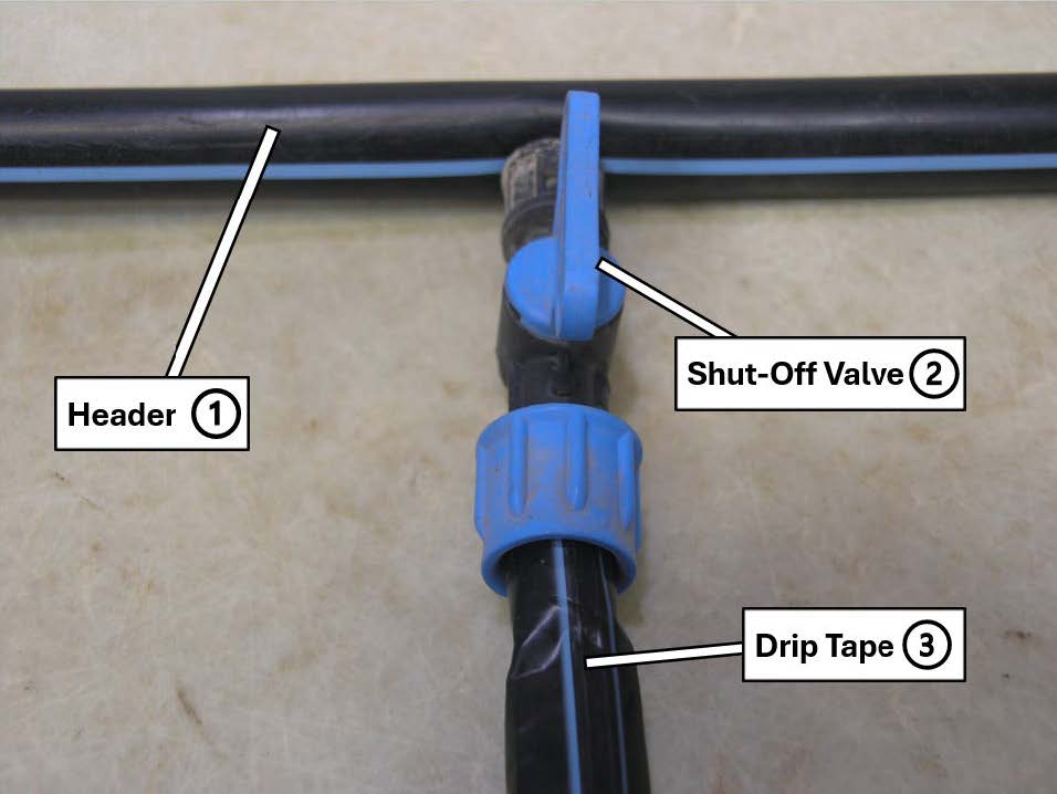
Drip tape is connected after the connectors have been attached to the header lines (Figure 6). Connecting involves loosening the nut and inserting the drip tape onto the outlet. The nuts are then tightened. (Note, some of these tighten to the left.) If installed correctly, tugging at the drip tape line should not allow the tape to detach. Sometimes it is easier to connect the tape when water is flowing. Drip tape is installed with the emitters facing upward. Some drip tape has lines on the top side to aid in installation. Applying landscape staples can ensure lines remain flat, with emitters facing upward, at the desired distance from the crop, and prevent the need to manually move them back into place for every irrigation event. However, drip lines should not be staked too tightly to allow for some movement.
Elbows and tee connectors can be used to redirect drip tape lines or bypass obstructions. Drip tape cannot be bent, as water flow will be reduced or stopped entirely. Using elbows and tee connectors where required can mitigate any interference with water distribution.
Couplings can be used to repair or reattach drip tape lines. When leaks occur, it is ideal to cut the drip tape at the location of the leak (pressurized lines make leaks more visible). Be sure to inspect the drip tape line and avoid cutting emitters, as couplings will not seal properly over cut emitters. Multiple couplings are not a solution to avoid replacing the drip tape lines, as they can reduce water application uniformity.
Each drip tape line is terminated using an end connector, a connector with an end cap, a shut-off valve, or by folding the end into a piece of tape. End connectors or caps can be removed or end shut-off valves opened to flush the line for routine maintenance. Flushing lines periodically is an important and often neglected aspect of drip irrigation system design. Flushing is especially important when using secondary water or in systems with added amendments (e.g., fertigation systems). A landscape staple near the end of the drip tape line will ensure that it stays in place. Tying the end of the line into a knot is not recommended, except for temporary repairs.
Tools for System Management and Repair
Improving or Supporting System Operation
Beyond the initial tools needed to set up an irrigation system, supplemental kits and tools, though not required, are handy and practical to help manage, install, repair, save money, and address issues that may occur during the operation of a drip irrigation system (Table 5).
Table 5: Tools for Repairing a Drip Tape Irrigation System or Streamlining Operation and Installation
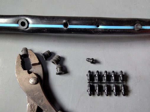
Goof plugsUsed to seal holes in header lines if drip lines were removed or mistakes occur. The most common size is ¼ inch; larger sizes of ⅝ and ⅞ inch are available for other types of drip tape. |
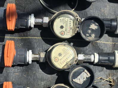
Flow metersThese measure the volume of water applied in gallons, GPM, GPH, LPM, or LPH. Typically, they are placed before the pressure regulator; placement after the filter is preferred. Common ¾-inch to 2-inch sizes are made of plastic, and are analog or digital. |
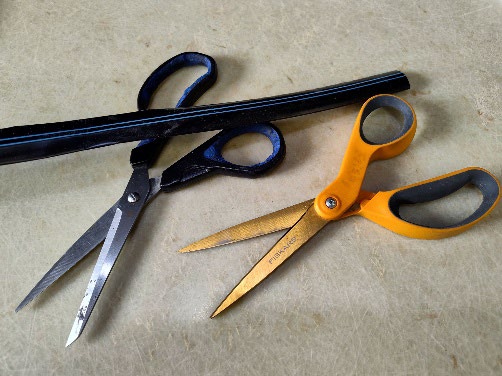
ScissorsUsed to cut drip tape and expand the ends of drip lines for connectors, scissors are not recommended for cutting header lines. Standard stainless steel scissors are ideal for performing drip tape cutting. |
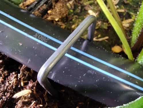
Landscape staplesThese secure the drip tape and main headers in place. Larger staples are needed for headers to ensure proper anchoring. For headers, use 12-inch-long, 2-inch-wide staples, and for drip tape, use staples 6 to 8 inches long and 1 inch wide. |
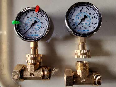
Pressure gaugeThese provide a visual guide for observing system pressure and detecting clogging or pressure fluctuations. A gauge 0 to 30 PSI is sufficient for drip tape systems running at 8 to 15 PSI. Liquid-filled or digital gauges are available but vary in pricing. |
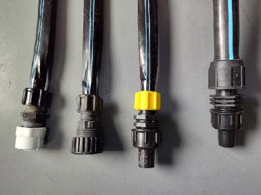
Tape ends and flush valvesManually or automatically, flush valves assist in removing debris from drip tape lines during active operation. Valves eliminate the need to remove an entire end cap and reinstall it. For drip tape, ⅝-inch flush valves are available, whereas header lines ¾ to 1 inch are options. |
- Goof plugs seal holes in poly pipes in case of hole-punching errors or when changing drip tape line placement. Goof plugs are often double-sided, with one side standard for punched holes; ¼ inch is the most common. The secondary side is used for holes that may have been enlarged by (take-off) connectors. Goof plugs are not an alternative to fixing header poly tubing, but a tool to plug unwanted holes from an error or (take-off) connector removal.
- Flow meters can be used to measure the volume of water applied. Water applied can be displayed as: gallons, liters per hour (LPH), liters per minute (LPM), GPM, or GPH. Typically, flow meters are installed inline before the pressure regulator. If multiple headers are used, it may be useful to include additional flow meters. Flow meters require a straight length of pipe both before and after for accurate measurement. They should not be installed directly after a valve, regulator, elbow, tee, filter, or reducer.
- Sharp, clean scissors are a practical tool used for cutting the drip tape to the desired length. Cuts must be straight and not angled. Scissors can also be used to spread open the cut end of the drip tape lines before attaching to (take-off) connectors or end plugs. Similarly, scissors can facilitate repairing the drip tape by cutting where a leak is occurring and installing a coupling.
- Landscape staples keep aboveground drip tape lines in place. Lines move around when coming under pressure and may twist, changing the orientation of the emitters so they face downward. Placing landscape staples at regular, 20-foot intervals will ensure that lines remain in place. A 6- to 8-inch length of tubing with a 1-inch-wide landscape staple works well. Do not push the staple all the way to ground level, as there should be some room for the drip tape to expand when under pressure and with changes in temperature. Header lines can also benefit from securing with staples. Usually, a 12-inch-long, 2-inch-wide staple will provide enough support to keep the tubing in place.
- A pressure gauge is used to verify the required pressure of the water supply. A pressure gauge in the line will determine the dynamic pressure when the system is on. A gauge before and after the filter will show any pressure drops when the filter needs cleaning (Figure 7). A gauge after the regulator determines if the regulator is working and if the header or subheader is operating at the proper pressure (10–15 PSI). A gauge at the end of the drip tape line will show the pressure in the drip tape (at least 8 PSI). If the gauge reading is abnormal, check that the gauge is working. Gauges only last a couple of years and should not be allowed to freeze.
Kits are an alternative to selecting individual components. A typical drip tape kit will include poly pipe tubing, connectors, and supplementary instructions. Kits may be an optimal choice for beginners, those with small spaces, and those wanting to keep a minimal system design.
Final System Optimization
Preventative measures at installation and ongoing management strategies reduce system faults and optimize performance at operation:
Water audits can help measure how much water can be released at a time, evaluate distribution uniformity, and estimate how much water can be applied in a zone over a given time period. Audits can uncover leaks, pressure drops, filter clogging, or kinks in header or drip tape lines. Flow rate and pressure decrease from the friction created as water is transported through the lines or redirected from the elbow and tee connectors. USU Extension’s “The Do-It-Yourself Guide to Backyard Drip Irrigation” demonstrates how to evaluate the amount of water a source can supply, which is a good first step before outlining and sectioning beds.
- Ensuring pressure does not decrease is important while irrigation is active. A great way to identify pressure fluctuations or unidentified clogging is to attach a pressure gauge before and after the filter (Figure 7). Debris may be present in the filter if there is a noticeable pressure drop. For example, if the pressure gauge before the filter reads 15 PSI and the one after the filter reads 5 PSI, it is safe to assume the filter needs cleaning or replacing.
- Avoid having drip tape lines fold, ensure they remain flat, and have emitters facing up away from the soil. A simple walkthrough before turning on the system can prevent any water blockages and identify where landscape staples may be needed.
- Though not always possible, working the soil to create a homogeneous, flat surface can improve uniform water infiltration in the soil, decrease runoff, or prevent ponding water from slopes or slumps. Uneven water distribution may be alleviated by using low-flow drip tape, drip tape line adjustments, or substituting with pressure-compensating drip tape. However, pressure-compensating emitters are usually only needed when the ground is sloped or undulating (up and down).
- At the beginning of a new field season or crop rotation, flush out drip lines and header lines to remove any build-up of debris buildup or find any leaks that may be present. Flushing lines at the end of a season is also important.
- Replacement is required for drip tape lines of 5 mil wall thickness annually, or after a crop rotation if damaged from the previous crop.
Summary
Drip tape irrigation systems are an efficient and customizable way to deliver water to crops, conserve water, and make optimal use of small spaces. Systems may use culinary or secondary water but differ in routine maintenance. Connecting to a water source starts with a backflow preventer, filter, and pressure gauge to ensure reliable, stable, and appropriate water distribution at a pressure of 10 to 15 PSI. Performance of header and drip tape lines depends on available pressure, system design and layout(s), as improper installation and pressure limitations from water sources can reduce the overall efficiency and effectiveness of water applied. Cut flower crop selection and spacing will influence drip tape placement and emitter spacing to optimize water delivery at the root zone. Differentiating between components, product specifications, and unique functions will help create the desired system expectations and operation for longevity and efficiency, crop success, and minimizing water loss.
References
Black, B., Cardon, G., & Miller, Z. (2026). Chapter 12: Irrigation. In Intermountain commercial tree fruit production guide, 2026–27 (pp. 177–182). USU Extension.
Drip Depot. (2021). All about PVC fittings, types explained.
Hansen, S., Beddes, T., Barker, B., & Butler, A. (2023). Water recommendations for vegetables. [Fact sheet]. USU Extension.
Gunnell, J., Beddes, T., & Barker, B. (2025). The do-it-yourself guide to backyard drip irrigation [Fact sheet]. USU Extension.
Kuhns, M. (2026). Drip irrigation of trees [Fact sheet]. USU Extension.
Rowell, B. (2019). Go with the flow: Simple calculations for drip irrigation [Fact sheet HO-122]. University of Kentucky Cooperative Extension.
Schuch, U. (2006). Drip irrigation: The basics [Fact sheet AZ1392 2016]. University of Arizona Cooperative Extension.
Seeborg, C., Stock, M., Rodriguez, A., Barker, B., & Meyer, J. (In process). Part II: Sustainable practices for cut flower irrigation.
USU Small Farms Lab. (2026). Cut flower + foliage production [Fact sheets].
Sanford, S., & Panuska, J. (2018). The Basics of micro irrigation (Publication No. A4119). University of Wisconsin Extension.
Stock, M., Maughan, T., & Grossl, P. R. (2020). Urban garden soils: Testing and management [Fact sheet] USU Extension.
Taghvaeian, S. (2017). Drip irrigation systems [Fact sheet No. BAE-1511]. Oklahoma State University Extension.
Volesky, N., Murray, M., Olds, A., Snarr, A., Carey, B., Drost, D., Alston, D., Cannon, C., & Nischwitz, C. (2024). Utah vegetable production guide (5th ed.) [Guidebook]. USU Extension.
Whiting, D., Jones, K., & Murgel, J. (2023). Watering efficiently [Fact sheet]. Colorado State University Extension.
Disclaimers and Acknowledgments
Using original figures and tables without written permission from the authors is prohibited. The authors did not use generative AI in creating this content, and it is solely the work of the authors. This content should not be used for the purposes of training AI technologies without express permission from the authors. This project was funded by the Western Sustainable Agriculture Research & Education, and the Utah Department of Agriculture and Food Specialty Crop Block Grant. The information reflects the views of the authors and not funding agency.

June 2026
Utah State University Extension
Peer-reviewed fact sheet
Authors
Alex Rodriguez, Melanie Stock, James Frisby, and Burdette Barker

Melanie Stock
Urban and Small Farms Specialist
PSC Dept

Burdette Barker
Irrigation
Related Research